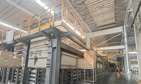
Glass Industry Thermal Insulation Solutions
A glass melting furnace operates at 1,570-1,600°C in the melter zone, with campaigns that frequently span 8-15 years. Crown, sidewall, and bottom refractories all depend on multi-layer glass furnace insulation to manage heat loss while protecting the refractory lining from excessive thermal stress. The insulation design must balance two competing risks: over-insulation can drive the refractory hot face beyond its safe service temperature, while under-insulation wastes fuel and overheats the working environment. Mingfa calcium silicate products, manufactured in our 108,000 m² facility in Laizhou, Shandong, provide density-controlled formulations for glass melting furnace backup and float glass insulation applications across the full furnace campaign life.
1. Glass Melting Furnace Insulation Needs
Key Takeaways
- Insulation Performance: Two-layer calcium silicate systems reduce glass furnace crown shell temperature from 180-200°C to 80-100°C.
- Campaign Durability: Glass melting furnace campaigns span 8-15 years — the insulation system must maintain thermal performance and mechanical integrity for the full campaign without degradation.
- Process Quality: Forehearth insulation improves glass gob weight consistency by preventing cold spots at channel walls, directly impacting forming quality.
- Mingfa Capability: Low-iron calcium silicate grades (Fe2O3 <0.4%) are available for flint (clear) glass production, with XRF analysis per production batch.
Mingfa Lab Verified (2024): All specifications listed are validated through in-house testing at our Shandong QC laboratory per ASTM C518 (thermal conductivity), ASTM C165 (compressive strength), and ASTM C356 (linear shrinkage). Batch test certificates issued with every order. View our testing methodology
The melter is the highest-temperature zone in any glass production line. Refractory selection is driven primarily by glass contact compatibility and corrosion resistance, not thermal insulation value. Silica brick crowns, AZS (alumina-zirconia-silica) fused cast sidewall blocks, and zircon-based bottom paving all have thermal conductivities 10-50 times higher than a properly specified calcium silicate backup board. Without insulation, a glass furnace loses a substantial fraction of its energy input through the refractory shell.
The design constraint is that each refractory material has a maximum service temperature at its hot face that must not be exceeded. Silica brick, used in most container glass and float glass furnace crowns, operates with a hot face near 1,600°C but must remain above approximately 600°C through its thickness to avoid cristobalite phase inversion, a volume change that causes spalling and catastrophic failure. AZS fused cast sidewall blocks have different constraints: the glass contact face runs near 1,550°C, but excessive backup insulation can allow the hot face to exceed the exudation temperature of the AZS glassy phase, accelerating corrosion. Bottom refractories face hydrostatic head pressure from the glass melt plus compressive load from the entire refractory structure above.
2. Crown & Sidewall Backup Insulation
Furnace Crown: Two-Layer Insulation System
The furnace crown presents the most thermally demanding insulation application in a glass plant. Constructed of silica brick 300-350 mm thick spanning the full melter width in a sprung arch, the crown radiates continuous heat loss over the entire melter area. Mingfa specifies a two-layer calcium silicate crown insulation system:
- Layer 1 (against silica brick). 50 mm MFBL-300 board at 300 kg/m³ density. This grade handles the interface temperature (typically 600-800°C at the silica brick cold face) without thermal degradation. Higher-density boards in this position would conduct more heat into the outer layer; lower-density boards risk shrinkage at sustained temperature.
- Layer 2 (outer). 50 mm standard calcium silicate board (HCS-23) at 230 kg/m³ density, providing the bulk of the thermal resistance.
This two-layer arrangement typically brings crown outer shell temperature from 180-200°C (uninsulated) down to 80-100°C. The silica brick hot face remains above the cristobalite inversion threshold of approximately 600°C, with a safe margin over the full insulation thickness.
Sidewall: Multi-Layer with AZS Compatibility
Glass furnace sidewalls use a multi-layer construction where AZS fused cast block (typically 200 mm) forms the glass contact layer, backed by insulation that respects AZS temperature limits:
AZS Fused Cast (200 mm) + MFBL-500 Board (50 mm, 500 kg/m³) + HCS-23 Board (50 mm, 230 kg/m³)
The higher-density MFBL-500 is specified because sidewall insulation carries some compressive load from the refractory above and vibration during furnace operation can settle lower-density boards. MFBL-500 has compressive strength exceeding 5 MPa.
3. Bottom & Regenerator Insulation
Furnace Bottom: Load-Bearing Insulation
Furnace bottom insulation serves two purposes: reducing downward heat loss into the substructure and preventing the steel support framework from reaching temperatures that reduce its load-bearing capacity. The bottom construction is heavier than the crown:
Zircon Paving (100 mm) + MFBL-800 Board (75 mm, 800 kg/m³) + HCS-23 Board (50 mm) + IFB (65 mm) + Steel Bottom Plate
MFBL-800 is specified at the critical load-bearing position because the combined weight of glass melt and refractory creates compressive stress that would crush lower-density insulation. MFBL-800 has compressive strength exceeding 8 MPa at ambient, with less than 2% compression under typical furnace bottom loads. Structural steel begins to lose design strength at approximately 150°C; the insulation system must keep the steel bottom plate below this threshold.
Regenerator Insulation
Regenerator chambers cycle between receiving hot exhaust gases and preheating combustion air with cycle times of 20-30 minutes. The checkerwork (refractory bricks stacked to absorb and release heat) operates with top temperatures of 1,200-1,350°C and bottom temperatures of 400-600°C. Insulation in regenerator walls and the crown uses LG-Standard or MFBL-300 board depending on the zone temperature, with thickness designed to maintain shell temperature below 80°C.
4. Temperature Zone Strategy: Melter vs Refiner vs Forehearth
Different furnace zones require different insulation strategies based on operating temperature and glass conditioning requirements:
| Furnace Zone | Temperature | Insulation Strategy | Key Product |
|---|---|---|---|
| Melter | 1,570-1,600°C | Maximum insulation where safe for refractory. Two-layer crown and sidewall systems. Hot face temperature calculations mandatory. | MFBL-300 + HCS-23 (crown); MFBL-500 + HCS-23 (sidewall) |
| Refiner / Working End | 1,300-1,450°C | Moderate-to-high insulation. Lower glass temperature means refractory hot face constraints are easier to satisfy. Thicker insulation possible. | MFBL-300 + HCS-23 |
| Forehearth | 1,100-1,300°C | Insulation for temperature uniformity. Critical for gob weight consistency at forming. Prevent cold spots at channel walls that create thermal gradients in the glass stream. | MFBL-300 + HCS-23 (50 mm + 40 mm) |
| Throat / Riser | 1,200-1,400°C | Insulate to maintain glass temperature through the throat. Prevent glass cooling that would increase viscosity and restrict flow. | MFBL-300 or LG-Standard (HCS-23) |
References: [1] ASTM C533-17(2023); [2] EN 14306:2015+A1:2018; [3] GB/T 10699. Full certification details
Forehearth temperature uniformity is especially important for glass conditioning. A temperature difference of just 5°C across the channel width produces measurable differences in glass viscosity, which translates directly to gob weight variation at the feeder. Plants that have retrofitted forehearth insulation with Mingfa products report gob weight standard deviation reductions at the forming machine. Consistent insulation prevents cold spots at channel walls that would otherwise create thermal gradients in the glass stream.
5. Case Reference: Linyi Laning Jinxi Tai Glass Production Line
Mingfa supplied float glass insulation products for the Linyi Laning Jinxi Tai Glass production line in Shandong Province, China. The project involved a float glass furnace producing architectural glass.
Linyi Laning Jinxi Tai Glass Insulation Results
The project specified MFBL-300 board (50 mm) plus standard calcium silicate board (50 mm) for the furnace crown, MFBL-500 (50 mm) for sidewall backup, and MFBL-800 (75 mm) for the bottom insulation layer. Products were supplied with full batch test certificates including density, compressive strength, and thermal conductivity data. The furnace operator reported consistent shell temperature reduction and stable forehearth glass conditioning after the insulation was commissioned.
6. Product Selection Guide
| Application | Product | Model | Density | Key Parameter |
|---|---|---|---|---|
| Furnace crown (layer 1, hot face) | Medium-Density CS Board | MFBL-300 | 300 kg/m³ | 650°C continuous; handles brick cold face temp |
| Furnace crown (layer 2, outer) | Standard CS Board | HCS-23 | 230 kg/m³ | Bulk thermal resistance |
| Sidewall backup | Medium-Density CS Board | MFBL-500 | 500 kg/m³ | Compressive strength >5 MPa |
| Bottom backup (load-bearing) | High-Density CS Board | MFBL-800 | 800 kg/m³ | Compressive strength >8 MPa |
| Forehearth / working end | CS Board (2-layer) | MFBL-300 + HCS-23 | 300 / 230 | Temperature uniformity critical |
| Regenerator walls | LG-Standard or MFBL-300 | HCS-23 / MFBL-300 | 230-300 | Zone-dependent; bottom vs top temp |
| Flint glass (low iron requirement) | Low-Iron CS Board | HCS-23-LI | 230 kg/m³ | Fe2O3 <0.4% |
For flint (clear) glass production, Mingfa supplies low-iron calcium silicate grades with Fe2O3 content controlled below 0.4%. These grades use raw materials from quarries with naturally lower iron content and are manufactured in dedicated production runs to avoid cross-contamination. XRF analysis of iron content is provided per production batch.
7. Installation Considerations
Thermal Expansion Management
Calcium silicate board has a coefficient of thermal expansion of approximately 5-6 × 10⁻⁶/K. For a furnace crown spanning 8 meters at 600°C (cold face), the insulation layer expands approximately 27-32 mm. The 2-3 mm expansion gaps between boards accommodate this movement. Boards must be butt-jointed, not compressed against each other, to allow for expansion without buckling.
Anchoring Systems
- Crown insulation: Stainless steel studs (M6, 35-40 mm) welded to the steel crown shell at 300 × 300 mm centers. Self-locking nuts with washers (minimum 40 mm diameter) secure the two-layer board system. Ensure studs do not penetrate silica brick, they stop at the board-to-brick interface.
- Sidewall insulation: Studs at 300 mm centers. MFBL-500 board is pressed over studs and secured with washers and lock nuts. Standard board (HCS-23) is placed over the MFBL layer with staggered joints and secured with a second washer on the same studs.
- Bottom insulation: Dry-lay with staggered joints. The weight of paving blocks and glass melt above secures the boards. No studs required for bottom installation.
Moisture Control
Calcium silicate board must be stored dry on site. Boards that have absorbed moisture during storage or installation must be dried before furnace heat-up. Wet insulation produces steam during initial heating, which can condense in the refractory and cause spalling. Store boards under cover (tarpaulin or indoor storage) and protect from rain during the installation period.
Low-Iron Handling for Flint Glass
Low-iron boards must be handled separately from standard boards to avoid iron contamination. Use dedicated cutting tools, separate storage areas, and clean gloves. Even small amounts of standard-grade dust on low-iron board surfaces can introduce iron contamination that produces green tint in flint glass.
Engineer Your Glass Furnace Insulation System
Tell us your furnace type, melter temperature, crown construction, and campaign target. Our technical team will calculate the temperature gradient through each layer and recommend the optimal insulation configuration, typically within 24 hours.
Request Technical ConsultationFurther Reading
- Calcium Silicate Board Product Range , full specifications, density grades, and temperature ratings
- Technical Resources , thermal conductivity curves, compressive strength data, installation guidance
- Cement Kiln Insulation Solutions , similar multi-layer high-temperature approach
- Insulation Thickness Calculation Guide
- Industry Solutions Hub
- Calcium silicate vs insulating fire brick — glass furnace backup comparison
About the Author — Mingfa Insulation Technical Team
Mingfa Insulation engineering team — 34+ years calcium silicate R&D and manufacturing since 1991. ~20 national patents. lzmfgr@163.com