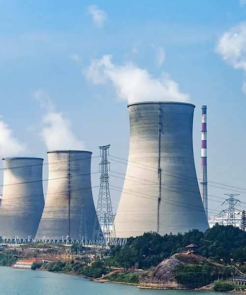
Power Generation Industry Thermal Insulation Solutions
Thermal power plants, coal, gas, biomass, and waste-to-energy, convert fuel energy to electricity through a steam cycle operating at temperatures up to 620°C. Insulation performance directly affects plant heat rate, measured in kJ/kWh. A 10°C increase in boiler casing temperature corresponds to approximately 0.1% additional fuel consumption, a figure that compounds across 8,000+ annual operating hours into millions of dollars. Mingfa power plant boiler insulation, steam turbine insulation, and flue gas duct insulation products are manufactured under ISO 9001 in our 108,000 m² facility in Laizhou, Shandong, with project documentation supporting compliance verification for international power plant construction standards.
1. Power Plant Insulation Overview
Key Takeaways
- Energy Impact: A 0.5% heat rate improvement from boiler insulation upgrades saves ~$810,000/year for a 600 MW coal unit — with insulation payback in 6-9 months.
- Scale Matters: Boiler casing area exceeds 8,000 m² for a 600 MW unit. Even fractional surface temperature reduction compounds into millions of dollars in annual fuel savings.
- Critical Piping: Main steam and hot reheat piping at 540-620°C requires 80-150 mm calcium silicate insulation thickness calculated per heat conservation specifications.
- Mingfa Reference: Calcium silicate boiler, piping, and flue gas duct insulation supplied to Shouguang Chenming Power Plant (Shandong) with full batch certification including ASTM C518 thermal conductivity data.
Mingfa Lab Verified (2024): All specifications listed are validated through in-house testing at our Shandong QC laboratory per ASTM C518 (thermal conductivity), ASTM C165 (compressive strength), and ASTM C356 (linear shrinkage). Batch test certificates issued with every order. View our testing methodology
Power generation spans multiple fuel types and plant configurations, each with distinct insulation requirements:
Coal-Fired
Pulverized coal or CFB boilers. Largest insulated surface area (8,000+ m² for 600 MW). Furnace waterwall membrane temps 350-600°C. Fly ash environment. Calcium silicate non-combustibility critical for coal dust safety.
Gas-Fired / Combined Cycle
Gas turbine exhaust at 500-650°C to HRSG. Combined cycle 400-600 MW units. HRSG casing and ductwork insulation with aggressive construction schedules. Large-format panels preferred.
Biomass
Grate-fired or fluidized-bed boilers burning wood chips, agricultural residue, or MSW. Similar temperature profile to coal at smaller scale. Corrosion risk from alkali chlorides in some biomass fuels.
Waste-to-Energy
Municipal solid waste incineration. Boiler temperatures 400-500°C (superheater). Aggressive flue gas chemistry (HCl, SO2). Corrosion-resistant insulation specifications required. Calcium silicate inert in acidic environments.
A thermal power plant rejects approximately 55-65% of its fuel energy as heat, primarily through condenser cooling water and the flue gas stack. The remainder is lost through equipment surface heat losses from the boiler, piping, turbine, and auxiliaries. While surface heat loss is a smaller fraction of total energy rejection than the condenser, it is also the most directly controllable through insulation specification and maintenance.
2. Boiler Insulation: Walls, Roof, Bottom
The boiler is the largest insulated surface in a power plant. A 600 MW pulverized coal boiler has a furnace chamber approximately 20 m wide, 15 m deep, and 60 m high, with total external casing area exceeding 8,000 m². Insulation design must address distinct temperature zones:
Furnace Waterwall Zone
The gas-tight membrane wall contains the combustion zone. Tube metal temperatures are 350-450°C in the furnace lower section and 500-600°C in the superheater zone. Boiler insulation is installed behind the tube membrane, between the membrane and the outer casing:
- Burner zone & furnace nose: 50 mm LG-High Temperature (SCS-25, 1,100°C rating) where membrane surface temperatures exceed 800°C.
- General boiler enclosure: 50-75 mm LG-Standard (HCS-23, 230 kg/m³) for the majority of the casing where membrane temperatures are 400-600°C.
Superheater & Reheater Headers
Header compartments house tube-to-header connections where steam temperatures reach 540-620°C. These peak-temperature zones require LG-High Temperature board (SCS-25). The header compartment access doors also require insulation that can be removed and replaced during maintenance inspections.
Economizer Section
The economizer at the boiler rear pass operates at lower gas temperatures (300-500°C). Insulation can be thinner, typically 40 mm LG-Standard, because heat loss is lower and the economic justification for thicker insulation is reduced. The air heater outlet ductwork operates below 200°C and uses cost-optimized insulation thickness.
Boiler Roof & Penthouse
The boiler roof seals the furnace chamber and houses the pendant superheater and reheater tube penetrations. Roof insulation is critical because any hot spot on the roof allows dust accumulation that can self-ignite on the hot surface. Calcium silicate A1 non-combustibility is essential here: insulation that would smolder or smoke on a hot roof penetration creates a fire hazard that does not exist with calcium silicate.
Boiler Bottom Ash Hopper
The bottom ash hopper sees high mechanical wear from falling slag and clinker. MFGB composite brick (400-600 kg/m³) or LG-High Temp board with additional mechanical protection is specified for the hopper throat area.
3. Steam & Hot Water Pipe Insulation
The steam piping system is one of the most critical insulated systems in the plant. Each pipe category requires different insulation thickness per heat conservation calculations:
| Pipe Service | Temperature Range | Pressure (typical) | Insulation Thickness | Product |
|---|---|---|---|---|
| Main steam | 540-620°C | 16-25 MPa | 80-150 mm | Calcium Silicate Pipe Sections (HCS-P) |
| Hot reheat steam | 540-620°C | 4-8 MPa | 80-150 mm | Calcium Silicate Pipe Sections (HCS-P) |
| Cold reheat steam | 300-350°C | 4-8 MPa | 50-80 mm | Calcium Silicate Pipe Sections (HCS-P) |
| HP feedwater | 200-280°C | 18-25 MPa | 40-60 mm | Calcium Silicate Pipe Sections (HCS-P) |
| Extraction steam (HP heaters) | 350-450°C | 3-7 MPa | 50-80 mm | Calcium Silicate Pipe Sections (HCS-P) |
| Extraction steam (LP heaters) | 100-250°C | 0.1-1 MPa | 30-50 mm | Calcium Silicate Pipe Sections (HCS-P) |
| District heating supply/return | 90-130°C | 1-2.5 MPa | 40-80 mm | Pipe sections + vapor barrier (HCS-P-VB) |
References: [1] ASTM C533-17(2023); [2] EN 14306:2015+A1:2018; [3] GB/T 10699. Full certification details
Main steam and hot reheat piping handle the highest temperatures and pressures, a supercritical 600 MW unit operates main steam at 566°C/24 MPa or higher. Insulation thickness is calculated per heat conservation specification to limit heat loss to approximately 250 W/m² or less at the outer surface. Elbow sections are supplied as curved segments matching the bend radius to maintain uniform thickness around bends. The pipe sections are covered with aluminum weather jacketing (0.5-0.8 mm) for indoor installation or stainless steel for outdoor exposed runs, with all joints staggered to prevent water ingress.
4. Flue Gas Duct & Chimney Insulation
The flue gas duct insulation system serves two purposes: energy conservation (maintaining gas temperature for buoyancy and dispersion) and corrosion prevention (keeping duct wall temperature above the acid dewpoint):
Pre-Air Heater Duct
Economizer outlet to air heater inlet: 350-450°C. Insulate with LG-Standard board (50-75 mm) to prevent acid dewpoint condensation during low-load operation or cold startup. Large rectangular duct cross-sections require board secured with welded pin-and-washer systems.
Post-Air Heater Duct
Air heater outlet to ESP/baghouse to FGD: 120-180°C. Insulation maintains duct wall temperature above the acid dewpoint of approximately 120-140°C for coal-fired flue gas. Preventing acid condensation in the duct protects the steel from sulfuric acid corrosion.
SCR Reactor
Selective Catalytic Reduction reactor: 300-400°C. Insulation is critical to maintain catalyst bed at minimum activation temperature. If gas temperature drops below the activation threshold, NOx reduction efficiency falls and ammonia slip increases. 75-100 mm LG-Standard board on reactor casing.
FGD Absorber & Chimney
Flue Gas Desulfurization inlet: 120-180°C, moisture-saturated with residual SO2/SO3. Temperature drop control prevents pre-absorber condensation. Chimney liner insulation maintains buoyancy. Corrosion-resistant specifications apply throughout the wet FGD system.
5. Turbine & Auxiliary Equipment Insulation
Steam turbine insulation presents complex geometry challenges. The high-pressure and intermediate-pressure turbine outer casings have flanges, bolt heads, governor valve bodies, and extraction nozzle connections. Two insulation approaches are available:
- Board system. Large-format calcium silicate boards (LG-Standard or SCS-25) are cut and fitted to casing contours, secured by stainless steel bands or welded pin-and-washer systems. Board thickness is 50-100 mm depending on steam conditions. This method is standard for most turbine installations where the casing geometry allows board cutting and fitting.
- Insulation coating. For the most complex casing geometries with numerous bolt heads, irregular contours, and tight clearances, spray-applied or trowel-applied calcium silicate-based coating (HCS-Coat) builds up to the required thickness in multiple passes. The coating conforms to bolt heads and irregular contours without the cutting waste inherent in board application.
Auxiliary equipment insulation covers deaerators, feedwater heaters, blowdown tanks, and condensate system components. These operate at lower temperatures (100-350°C) and use thinner insulation (25-50 mm) but represent large total surface areas. Consistent insulation across auxiliary equipment contributes to overall plant heat rate improvement.
6. Case Reference: Shouguang Chenming Power Plant (Shandong)
Mingfa supplied power plant boiler insulation products for the Shouguang Chenming Power Plant in Shandong Province, China. The project scope covered boiler casing backup insulation, main steam and hot reheat piping insulation, and flue gas duct insulation for a coal-fired generating unit.
Shouguang Chenming Power Plant Results
Products supplied included LG-High Temperature board (SCS-25) for burner zone and superheater header compartments, LG-Standard board (HCS-23) for general boiler casing, and calcium silicate pipe sections for main steam and hot reheat piping. All products were supplied with full batch certification including density, compressive strength, and thermal conductivity per ASTM C518. The plant reported improved heat rate and reduced boiler casing surface temperature following the insulation upgrade.
7. Energy Efficiency & Emissions Reduction
Insulation upgrades on power plants produce measurable fuel savings with short payback periods. The numbers are large because power plants burn large quantities of fuel continuously:
Economic Analysis: 600 MW Coal-Fired Unit
| Annual generation (75% capacity factor) | 3,942,000 MWh |
| Heat rate | 9,500 kJ/kWh |
| Annual coal consumption | ~1.62 million tonnes |
| 0.5% fuel saving from improved insulation | 8,100 tonnes coal/year |
| Annual fuel cost saving (@ $100/tonne coal) | $810,000 |
| CO2 emissions reduction | ~20,000 tonnes CO2/year |
| Insulation material + installation cost | $400,000-$600,000 |
| Simple payback | 6-9 months |
At more conservative coal prices ($70/tonne), the annual saving still exceeds $560,000 and payback extends to 8-13 months, still well within the plant's remaining operating life. For gas-fired combined cycle plants, a 0.5% heat rate improvement on a 400 MW unit at $6/MMBtu gas generates approximately $180,000 annual savings, with proportionally lower installation costs maintaining similar payback periods.
Beyond direct fuel savings, power plant boiler insulation upgrades produce secondary benefits:
- Reduced CO2 emissions proportionate to fuel saving, important for plants subject to carbon pricing or emissions trading schemes
- Improved personnel safety through reduced ambient temperature in boiler house and turbine hall areas accessible to operators
- Reduced fire risk from A1 non-combustible insulation that does not accumulate fly ash dust or support smoldering combustion
- Lower HVAC load in enclosed power plant buildings where high ambient temperatures from uninsulated equipment stress ventilation systems
8. Product Selection by System
| Plant System | Operating Temp | Product | Model | Thickness |
|---|---|---|---|---|
| Boiler waterwall (burner zone) | 800°C+ (membrane) | LG-High Temperature Panel | SCS-25 | 50 mm |
| Boiler casing (general) | 400-600°C (membrane) | LG-Standard CS Board | HCS-23 | 50-75 mm |
| Superheater/reheater headers | 540-620°C (steam) | LG-High Temperature Panel | SCS-25 | 50-75 mm |
| Economizer section | 300-500°C (gas) | LG-Standard CS Board | HCS-23 | 40 mm |
| Main steam piping | 540-620°C | CS Pipe Sections | HCS-P | 80-150 mm |
| Hot reheat piping | 540-620°C | CS Pipe Sections | HCS-P | 80-150 mm |
| Cold reheat / feedwater piping | 200-350°C | CS Pipe Sections | HCS-P | 40-80 mm |
| Turbine casing (HP/IP) | 540-620°C | LG-Std Board or Coating | HCS-23 / HCS-Coat | 50-100 mm |
| SCR reactor casing | 300-400°C | LG-Standard CS Board | HCS-23 | 75-100 mm |
| Gas turbine exhaust duct | 500-650°C | LG-High Temperature Panel | SCS-25 | 50-75 mm |
| HRSG casing/ductwork | 80-600°C (progressive) | SCS-25 / HCS-23 | Per zone | 50-75 mm |
| Pre-air heater flue gas duct | 350-450°C | LG-Standard CS Board | HCS-23 | 50-75 mm |
| District heating pipe | 90-130°C | CS Pipe Sections + VB | HCS-P-VB | 40-80 mm |
Specify Insulation for Your Power Plant
Tell us your plant type, unit capacity, and steam conditions. Our engineering team will calculate the heat loss, recommend insulation thickness per energy code requirements, and provide a detailed quotation with full material certification, typically within 24 hours.
Request Technical ConsultationFurther Reading
- Calcium Silicate Product Range , complete specifications, density grades, temperature ratings
- Technical Resources , heat loss calculation tools, ASTM C680 methodology, installation guides
- Petrochemical Insulation Solutions , pipe insulation and CUI prevention approaches
- Insulation Thickness Calculation Guide
- Industry Solutions Hub
- Calcium silicate for MEP contractors — pipe insulation installation guide
- Calcium silicate for boiler engineers — boiler and steam system insulation solutions
About the Author — Mingfa Insulation Technical Team
Mingfa Insulation engineering team — 34+ years calcium silicate R&D and manufacturing since 1991. ~20 national patents. lzmfgr@163.com